English
 中文简体
Content
Industrial gas supply is a critical backbone for modern manufacturing, energy, and chemical infrastructure. Among the various gas separation methods available today, the Cryogenic Air Separation Plant (often referred to as an Air Separation Unit or ASU) remains the definitive industry standard for large-scale, ultra-high-purity production of oxygen, nitrogen, and argon.
As energy costs and environmental compliance mandates continue to evolve globally, modern cryogenic systems are designed to balance maximum gas purity with minimal specific power consumption.
1. Operating Principles of Cryogenic Air Separation
Cryogenic air separation relies on fractional distillation at ultra-low temperatures, taking advantage of the distinct boiling points of atmospheric gases at specific operating pressures:
- Oxygen (O2): -182.96 ℃ (90.19 K)
- Argon (Ar): -185.85 ℃ (87.30 K)
- Nitrogen (N2): -195.79 ℃ (77.36 K)
By compressing, purifying, cooling, and liquefying atmospheric air, distillation columns separate individual components based on their volatility differences. High-purity gaseous and liquid products are then withdrawn at various stages along the distillation stack.
2. Comparing On-Site Air Separation Technologies
Choosing the optimal gas supply system depends heavily on required gas volume, purity constraints, and load flexibility. The comparison below highlights where Cryogenic Air Separation fits in comparison with Non-Cryogenic alternatives (PSA and Membrane systems).
| Metric / Parameter | Cryogenic Air Separation Plant (ASU) | Pressure Swing Adsorption (PSA) | Membrane Gas Separation |
|---|---|---|---|
| Output Gas Options | Simultaneous O2, N2, Ar (Gas/Liquid) | Single gas stream (O2 or N2) | Nitrogen stream only |
| Purity Potential | Ultra-High (O2: 99.8%+, N2: 99.999%+, Ar: 99.999%+) | Medium-High (N2: up to 99.99%, O2: 93–95%) | Medium (N2: 95.0%–99.5%) |
| Production Scale | Medium to Massive (>1,000 Nm3/h up to 100,000+ Nm3/h) | Small to Medium (10 – 3,000 Nm3/h) | Small to Medium (5 – 1,000 Nm3/h) |
| Energy Efficiency at Scale | High economy of scale; lowest cost per unit volume | Optimal for low volume; energy scales linearly | Efficient for moderate purity requirements |
| Liquefaction Capability | Native capability to produce Liquid Oxygen (LOX), Nitrogen (LIN), Argon (LAR) | Not applicable | Not applicable |
| Primary Industrial Sectors | Metallurgy, Petrochemicals, Large Hospitals, Electronics | Laser cutting, Food packaging, Water treatment | Offshore oil rigs, Tire inflation, Vessel purging |
3. Core System Components in a Modern ASU
A complete Cryogenic Air Separation Plant integrates several specialized equipment subsystems to maintain steady thermodynamic control:
A. Main Air Compressor (MAC) & Pre-cooling Subsystem
The Main Air Compressor pulls ambient air through self-cleaning filters and compresses it to operating pressures. The compressed air is then cooled in a Direct Contact Cooler (DCC) using chilled water to condense out initial moisture content before further purification.
B. Molecular Sieve Purification Unit (PPU)
Removing trace contaminants—such as water vapor, carbon dioxide (CO2), and hydrocarbons—is critical prior to cryogenic cooling. Unremoved CO2 or moisture would freeze inside heat exchangers and cause severe flow blockages. The Purification Unit utilizes dual adsorbent beds operating under Temperature Swing Adsorption (TSA) or Pressure Swing Adsorption (PSA) cycles.
C. The Cold Box (Heat Exchangers & Expansion Turbines)
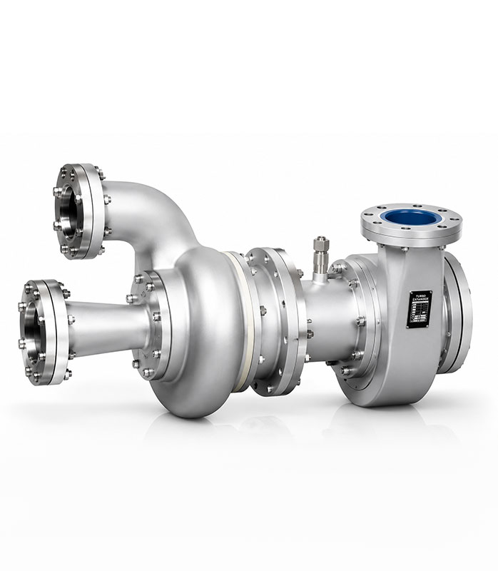
Encased in a heavily insulated structure known as the Cold Box, primary heat exchangers transfer thermal energy from incoming warm air to cold return gas streams. Cryogenic turbo-expanders generate the required refrigeration capacity through isentropic expansion, cooling air down to liquid temperatures.
D. Distillation Columns (High & Low Pressure System)
The cooled, partially liquefied air enters the primary distillation system. In a double-column configuration:
- Lower High-Pressure Column: Partially separates air into a nitrogen-rich vapor at the top and an oxygen-enriched liquid at the bottom.
- Upper Low-Pressure Column: Performs final fractionation to yield high-purity oxygen at the base and gaseous nitrogen at the top.
- Crude & Pure Argon Columns: Taps into vapor draws where argon concentrations peak (~7–10%), purifying argon to industrial grade.
4. Operational Innovations and Smart Gas Management
As industrial facilities move toward digital transformation, cryogenic air separation engineering is incorporating advanced automation to maximize plant yield and reduce total operational expenditure (OPEX):
- Advanced Process Control (APC): Dynamic algorithms constantly adjust air flow rate, turbine expansion speeds, and valve parameters based on changing real-time gas consumption demands.
- IoT & Remote Telemetry: Integrated sensors measure temperatures, pressure drop curves, and purity indicators across the system. Cloud dashboarding allows engineering teams to perform predictive diagnostics and prevent unexpected plant trips.
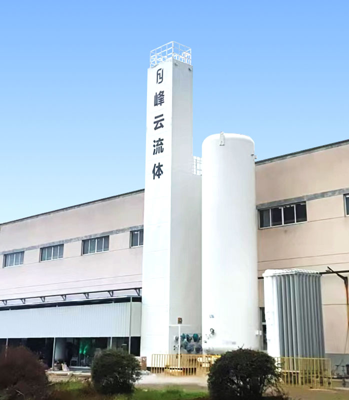
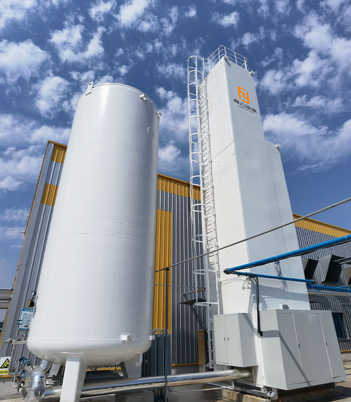
- Liquid Backup and Peak Shaving: By pairing cryogenic production plants with liquid storage tanks (LOX/LIN/LAR), operators can store excess liquid capacity during off-peak power hours and vaporize storage liquid during peak pricing hours.
5. Industrial Applications for Cryogenic Gas Output
6. Frequently Asked Questions (FAQ)
Partnering for Gas Infrastructure Success
When implementing complex industrial gas infrastructure, specialized manufacturing and technical execution are essential. Suzhou Fengyun Fluid Technology Co., Ltd. specializes in the design, manufacturing, delivery, and operation of cryogenic air separation systems for industrial oxygen, nitrogen, and argon. Backed by a team of 86 engineers and technical specialists, the company’s capabilities span air compression and separation station planning, air compression systems and air separation equipment sales and leasing, on-site gas generation, and outsourced technical services. Leveraging an IoT-enabled platform, Fengyun delivers smart gas supply solutions tailored to customer operations.
 Previous